Call Us: 775-882-2400 or Toll Free 800-654-5659
Call Us Today: 775-882-2400 or Toll Free 800-654-5659
High Power Probe Stations
High Frequency RF & mmW Probe Stations
Double Sided Probe Stations
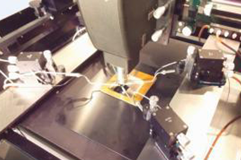
Automated Probe Stations
Thermal Probe Stations
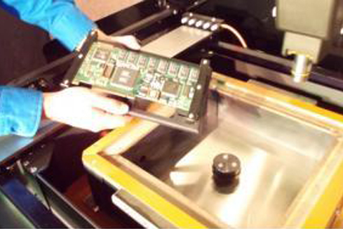
Board Level Testing
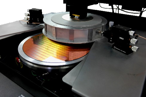
Wafer Level Reliability Probe Stations
Failure Analysis